Step -1:
Preparations: At first the workingspace should be prepared. Of course you need a soldering-iron (with a fine tip, anything between 0.5 mm and 1 mm) and solder (something between 0.3 mm and 1 mm). A fine side cutter and tweezers will be usefull, too. People without SMT-experience might want to read the SMT-Soldering-Instructions.
Step 0:
Completeness: The Kit should contain the following parts:
- 12 x 3300 Ohm Resistor
- 12 x 33 Ohm Resistor
- 1 x Atmel Mega88 Microcontroller
- 12 x BC848C Transistor
- 5 x 1500 Ohm Resistor
- 2 x 68 Ohm Resistor
- 1 x 100 nano Farad Capacitor
- 2 x 33 pico Farad Capacitor
- 8 x 1N4148 Diode
- 2 x Z3V6 Diode
- 1 x 10 mikro Farad Capacitor
- 3 x red LED
- 3 x green LED
- 3 x blue LED
- 3 x white LED
- 1 x mini USB Connector
- 1 x 16 MHz Crystal
Step 1:
soldering the 12 3300 Ohm resistors on the upper side
Step 2:
soldering the 12 33 Ohm resistors on the upper side

Step 3:
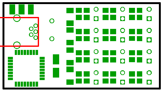
soldering the Atmel Mega88 microcontroller on the upper side Check the correct orientation of the microcontroller, the corner with the dot has to point to the corner of the PCB.
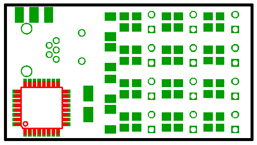
The PCB now has to be turned over.
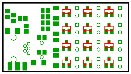
Step 4:
soldering the 12 transistors on the lower side
Step 5:
soldering the 5 1500 Ohm resistors on the lower side
Step 6:
soldering the 2 68 Ohm resistors on the lower side
Step 7:
soldering the 100 nano Farad capacitor on the lower side
Step 8:
soldering the 2 33 pico Farad capacitors on the lower side
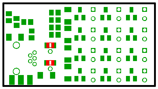
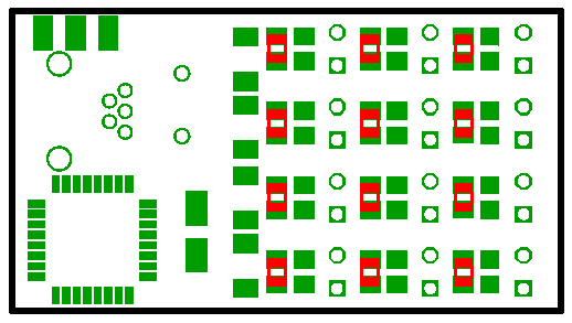
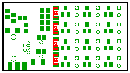
Step 9:
soldering the 4 1N418 diodes on the lower side Check the correct orientation of the diodes, when the USB-connector and the microcontroller are pointed to the left side, the black rings on the diodes have to point to the front edge of the PCB.
The PCB now has to be turned over.
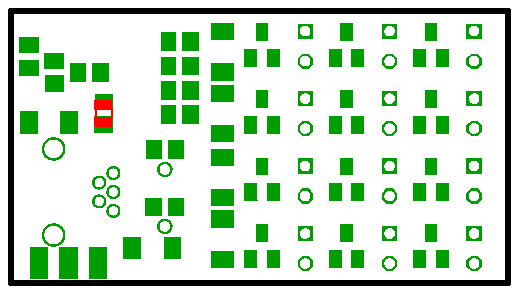
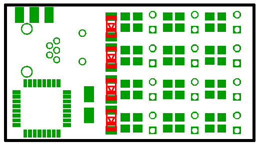
Step 10:
soldering the 4 1N418 diodes on the upper side Check the correct orientation of the diodes, when the USB-connector and the microcontroller are pointed to the left side, the black rings on the diodes have to point to the front edge of the PCB.
The PCB now has to be turned over.
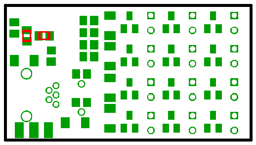
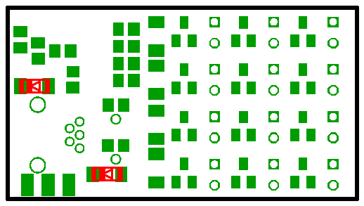
Step 11:
soldering the 2 3V6 z-diodes on the lower side Check the correct orientation of the diodes, rings on the diodes have to point in the same direction as the USB-connector.
The PCB now has to be turned over.
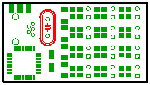
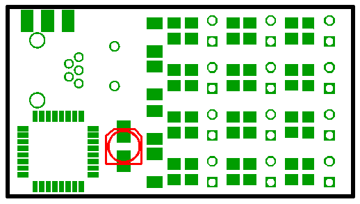
Step 12:
soldering the 10 mikro Farad capacitor on the lower side
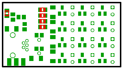
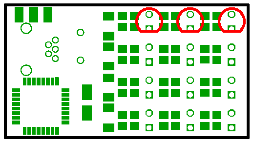
Step 13:
soldering the 3 red LEDs on the upper side Check the correct orientation of the diodes, the LEDs have to be plugged in from the upper side in a way that the flattened side (which also has the shorter leg) points to the front side of the PCB (which also hast the microcontroller).
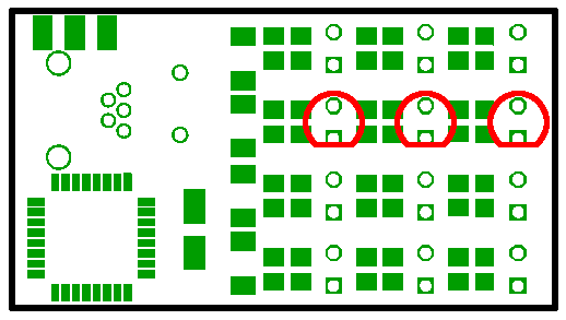
Step 14:
soldering the 3 green LEDs on the upper side Check the correct orientation of the diodes, the LEDs have to be plugged in from the upper side in a way that the flattened side (which also has the shorter leg) points to the front side of the PCB (which also hast the microcontroller).
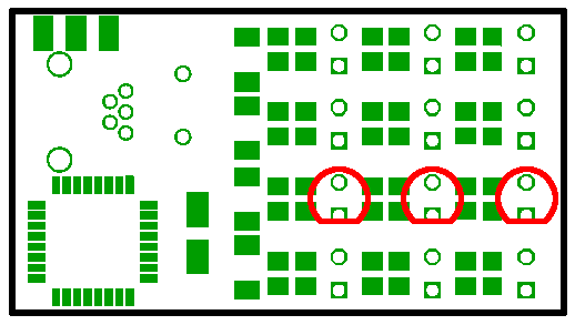
Step 15:
soldering the 3 blue LEDs on the upper side Check the correct orientation of the diodes, the LEDs have to be plugged in from the upper side in a way that the flattened side (which also has the shorter leg) points to the front side of the PCB (which also hast the microcontroller).
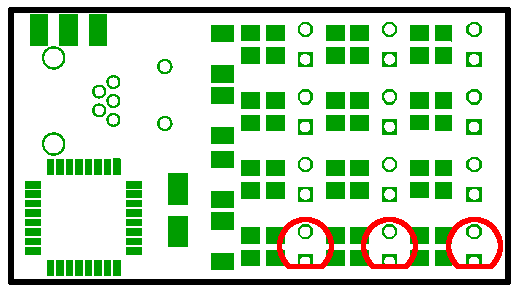
Step 16:
soldering the 3 white LEDs on the upper side Check the correct orientation of the diodes, the LEDs have to be plugged in from the upper side in a way that the flattened side (which also has the shorter leg) points to the front side of the PCB (which also hast the microcontroller).
Step 17:
soldering the mini USB connector on the upper side
Step 18:
soldering the crystal on the upper side