Step -1:
Preparations: At first the workingspace should be prepared. Of course you need a soldering-iron (with a fine tip, anything between 0.5 mm and 1 mm) and solder (something between 0.3 mm and 1 mm). A fine side cutter and tweezers will be usefull, too. People without SMT-experience might want to read the SMT-Soldering-Instructions.
Step 0:
Completeness: The Kit should contain the following parts:
- 1 x Atmel Mega88 Microcontroller
- 12 x 3300 Ohm Resistor
- 12 x 33 Ohm Resistor
- 5 x 1500 Ohm Resistor
- 2 x 33 pico Farad Capacitor
- 3 x 100 nano Farad Capacitor
- 11 x 1N4148 Diode
- 1 x Dataflash
- 1 x 10k Ohm Resistor
- 13 x BC848C Transistor
- 1 x 100 Ohm Resistor
- 2 x 3V6 Z-Diode
- 1 x 78L05 Voltageregulator
- 1 x MAX485
- 1 x 4,7 Ohm Resistor
- 1 x 16 MHz Crystal
- 9 x red LED
- 9 x green LED
- 9 x blue LED
- 9 x white LED
- 1 x TSOP1738
- 2 x 68 Ohm Resistor
- 1 x 2x3pin ISP-Connector
- 1 x 1x4pin USB-Connector
- 1 x IR-LED
- 1 x 4 terminal screw-clamp
Step 1:
soldering the Atmel Mega88 microcontroller on the upper side Check the correct orientation of the microcontroller, the corner with the dot has to point to the 4 pads of the power-connector.
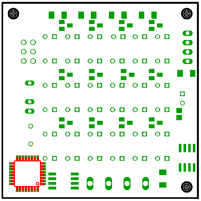
The PCB now has to be turned over.
Step 2:
soldering the 12 3300 Ohm resistors on the upper side
Step 3:
soldering the 12 33 Ohm resistors on the upper side
Step 4:
soldering the 4 1500 Ohm resistors on the lower side
Step 4a:
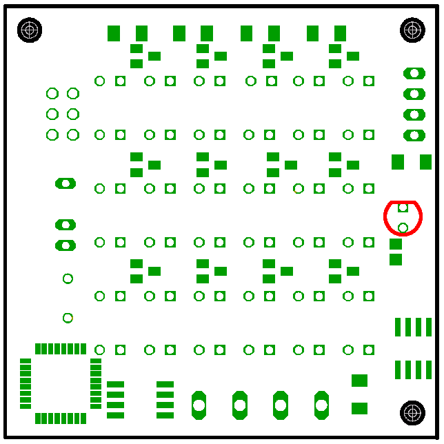
soldering the 1500 Ohm resistor on the lower side

Step 5:
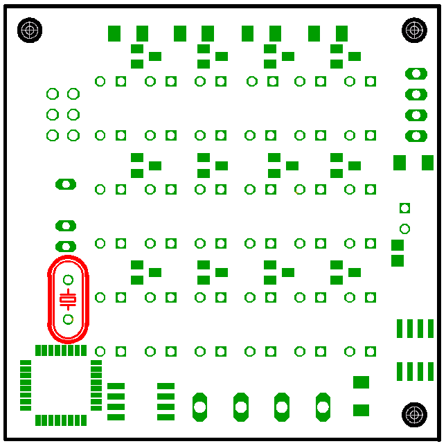
soldering the 2 33 pico Farad capacitors on the lower side
Step 6:
soldering the 3 100 nano Farad capacitors on the lower side
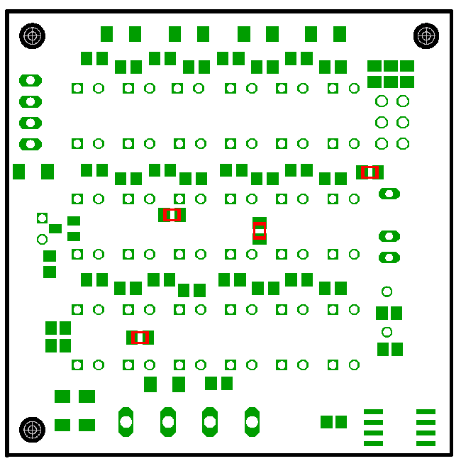
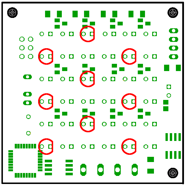
Step 7:
soldering the 5 1N4148 diodes on the lower side Check the correct orientation of the diodes, the rings of the 4 diodes in the upper row have to point to the 6 pads of the resistors of the USB. The Ring of the fifth diode has to point in the opposite direction.
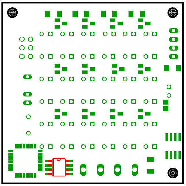
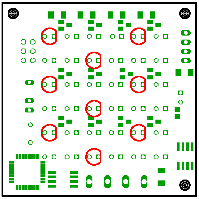
Step 7a:
soldering the 2 1N4148 diodes on the lower side Check the correct orientation of the diodes, the rings of the 4 diodes in the upper row have to point to the 6 pads of the resistors of the USB. The Ring of the fifth diode has to point in the opposite direction.
Step 8:
soldering the 10k Ohm resistor on the lower side
Step 9:
soldering the dataflash on the lower side Check the correct orientation of the Dataflash, the corner with the dot has to point to the corner of the PCB.
Step 10:
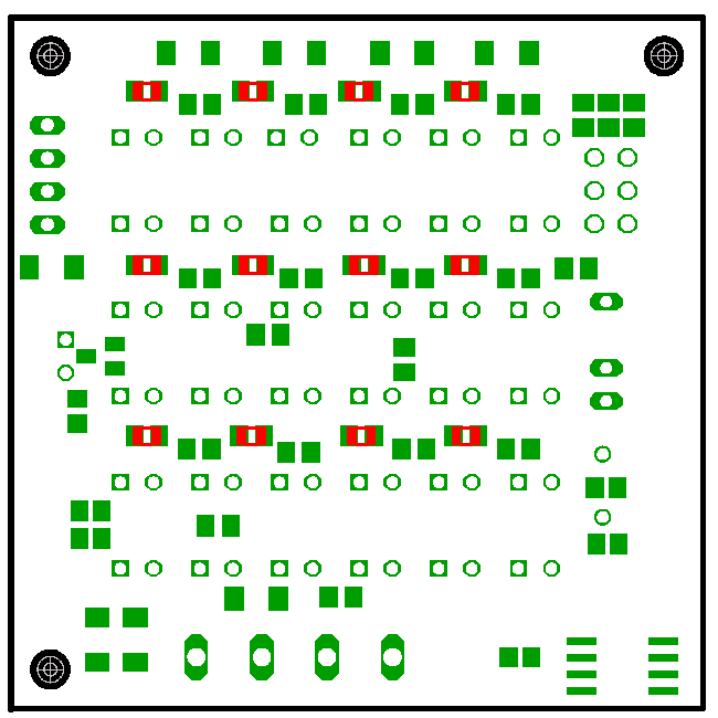
soldering the transistor on the lower side
Step 11:
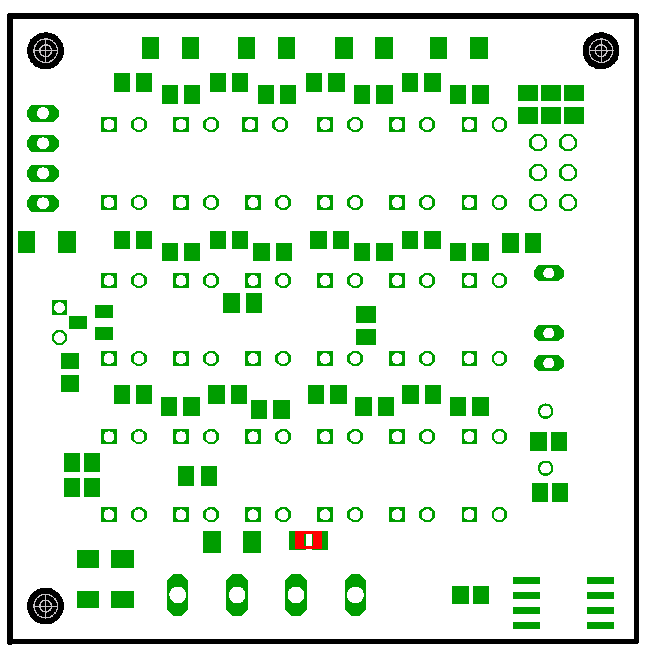
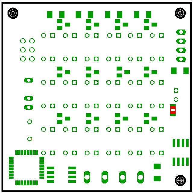
soldering the 100 Ohm resistor on the lower side
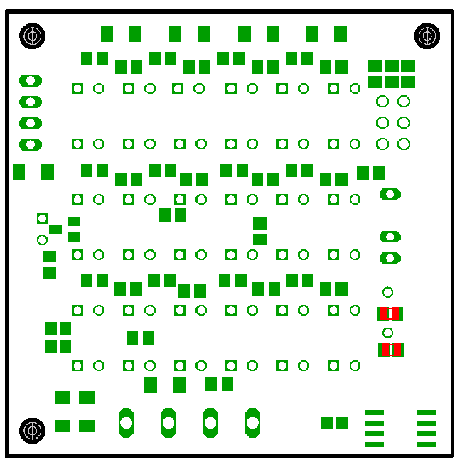
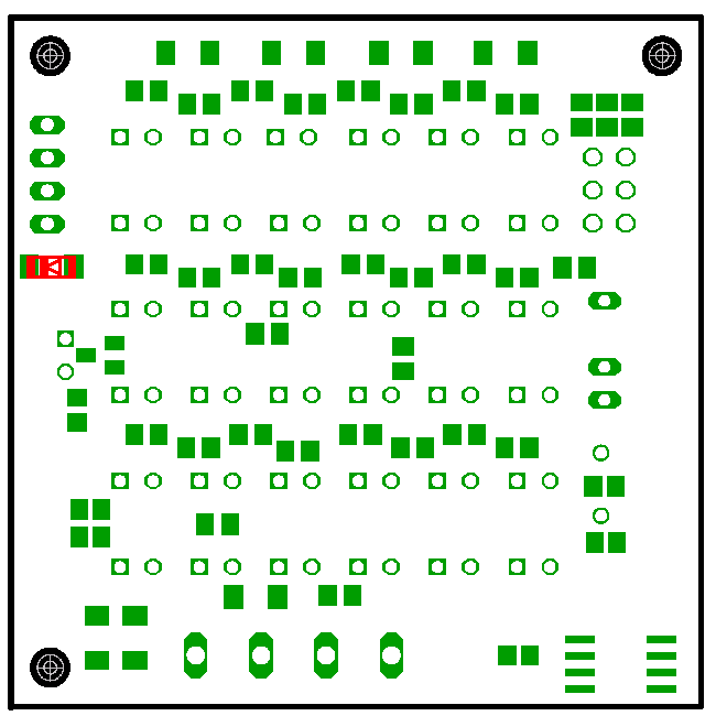
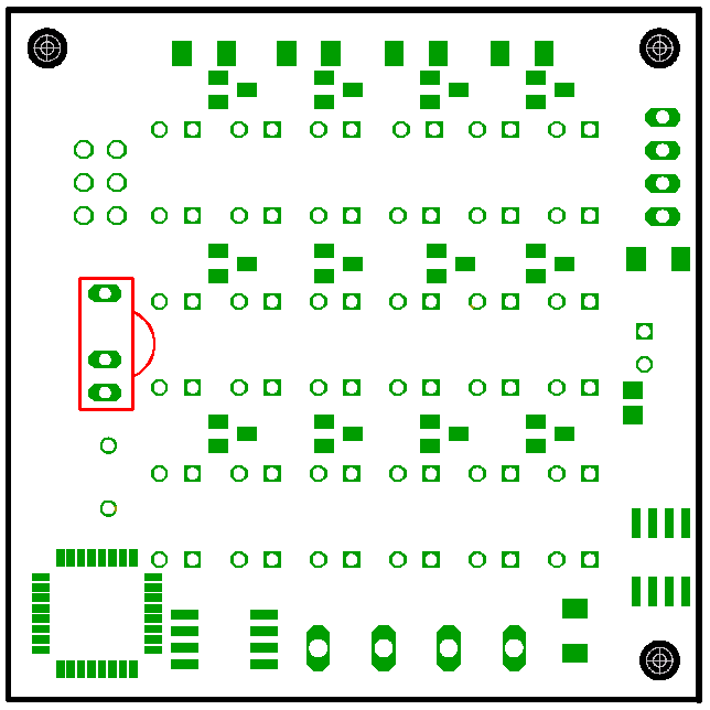
Step 12:
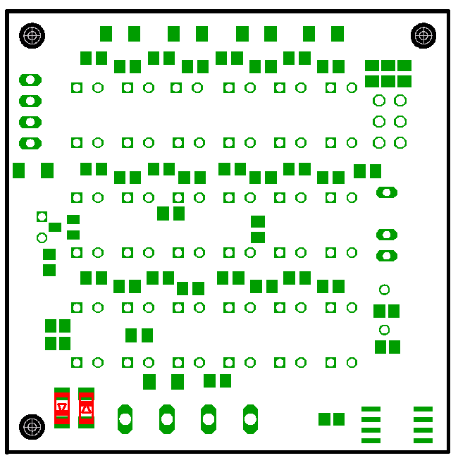
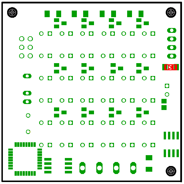
soldering the 3V6 Z-diodes on the lower side Check the correct orientation of the diodes, the ring of the diodes has to point to the edge of the PCB.
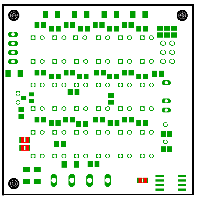
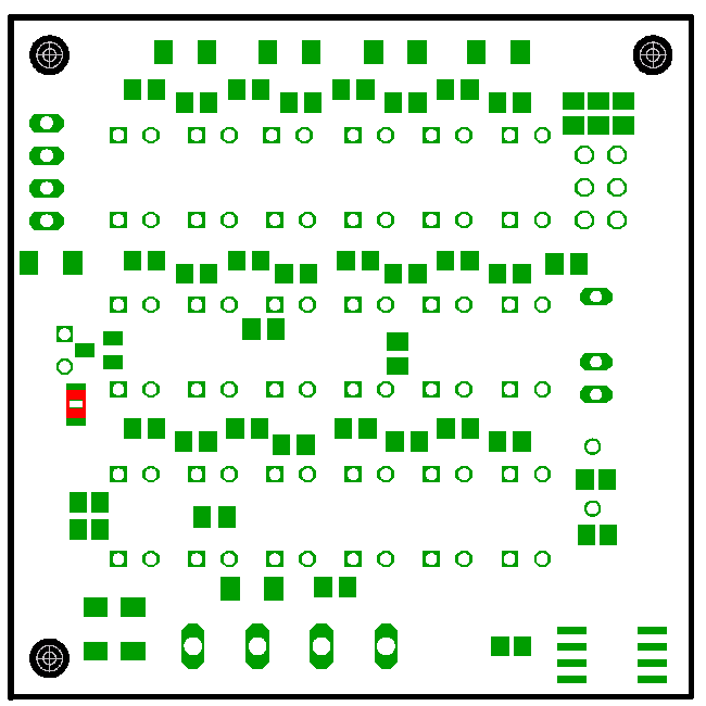
Step 13:
soldering the 2 68 Ohm resistors on the lower side

The PCB now has to be turned over.
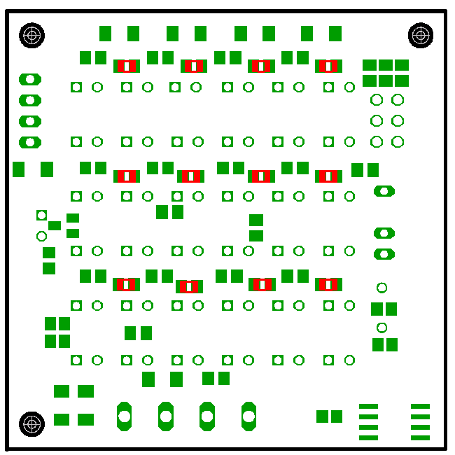
Step 14:
soldering the 12 transistors on the lower side

Step 15:
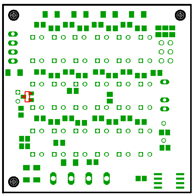
soldering the 78L05 Voltageregulator Check the correct orientation of the voltageregulator, the cut edge must point to the front-edge of the PCB.
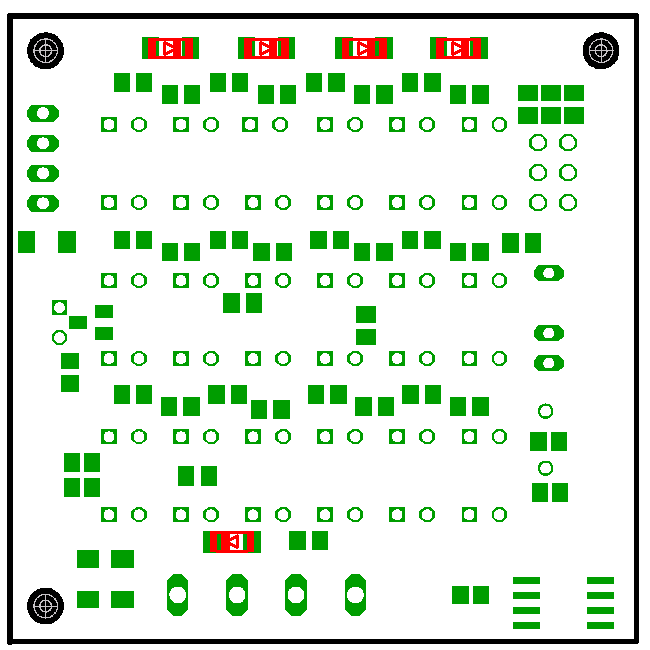
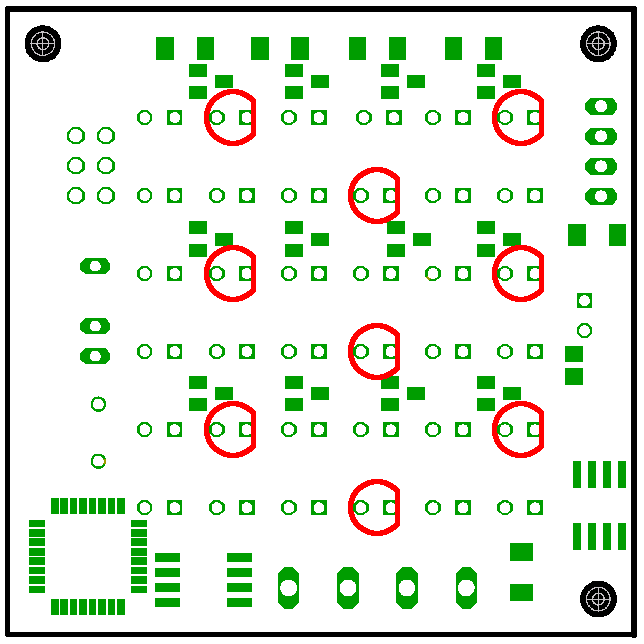
Step 16:
soldering the 2 1N4148 diodes on the lower side Check the correct orientation of the diodes, the rings of the 4 diodes in the upper row have to point to the 4 holes of the USB-connector. The Ring of the fifth diode has to point to the center of the PCB.
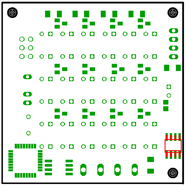
Step 17:
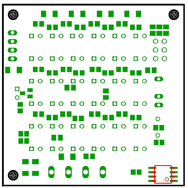
soldering the Max485 on the upper side Check the correct orientation of the Max485, the cut edge has to point to the atmel microcontroller.
Step 18:
soldering the 4.7 Ohm resistor on the upper side
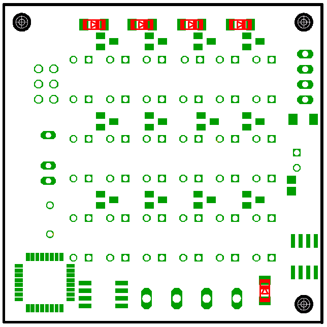
Step 19:
soldering the 3V6 Z-diodes on the upper side Check the correct orientation of the diodes, the rings have to point to the edge of the PCB.
Step 20:
soldering the crystal on the upper side
Step 21:
soldering the 3 red LEDs on the upper side Check the correct orientation of the diodes, the LEDs have to be plugged in from the upper side in a way that the flattened side (which also has the shorter leg) points to the pin-header of the USB-port.
Step 22:
soldering the blue LEDs on the upper side Check the correct orientation of the diodes, the LEDs have to be plugged in from the upper side in a way that the flattened side (which also has the shorter leg) points to the pin-header of the USB-port.

Step 23:
soldering the blue LEDs on the upper side Check the correct orientation of the diodes, the LEDs have to be plugged in from the upper side in a way that the flattened side (which also has the shorter leg) points to the pin-header of the USB-port.
Step 24:
soldering the white LEDs on the upper side Check the correct orientation of the diodes, the LEDs have to be plugged in from the upper side in a way that the flattened side (which also has the shorter leg) points to the pin-header of the USB-port.
Step 25:
soldering the TSOP1738 on the upper side Don't push in the TSOP all the way, but let it stand about 1 cm above the PCB, so it can be bent to diagonal line between the LEDs and the edge of the PCB.
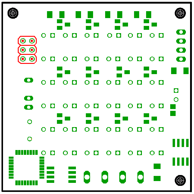
Step 26:
soldering the usb-connector on the upper side
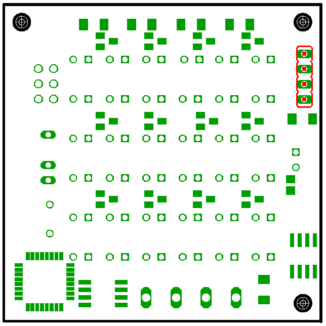
Step 27:
soldering the isp-connector on the upper side
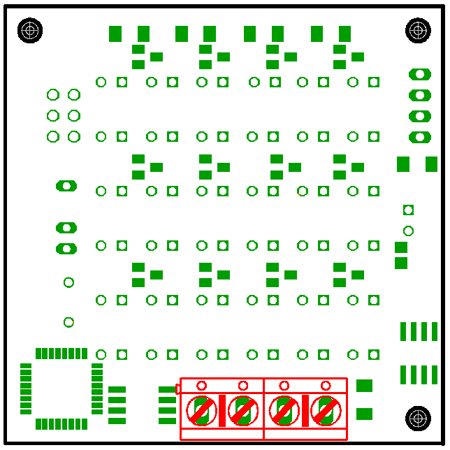
Step 28:
soldering the power and rs485-connector on the upper side
Step 29:
soldering the white LEDs on the upper side Check the correct orientation of the diodes, the LEDs have to be plugged in from the upper side in a way that the flattened side (which also has the shorter leg) points to the pin-header of the USB-port.