It is aviseable to keep your workingspace
SMT are surface mounted devices: Parts that are fixed on top of the PCB instead of having wires that are plugged through the pcb and soldered below it.
This has a few benefits:
- no bending and pushing wires through more or less matching holes
- no turning of the board with unsoldered parts to solder on the underside
- no cutting of the wires of the parts
- more mechanical stability
- smaller parts
- smaller (and cheaper) boards
The smaller size is sometimes seen as a problem, because it makes mounting of the parts harder.
The general idea when soldering SMT is the same as when soldering through-hole parts: With a connection between the pad on the PCB and the leg of the part is created with solder .
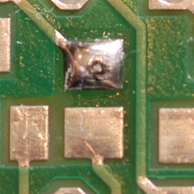
The easiest way is put solder on one pad on the PCB. If this isn't round, but has edges, add more flux.
solder on the first pad
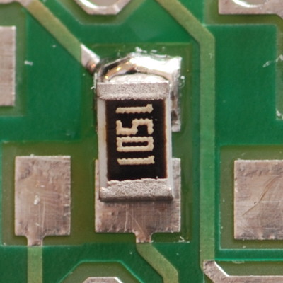
Then the part can be placed with tweezers in one hand on the PCB, while heating the blob of solder with the soldering iron in the other hand in a way that the part sinks into the solder.
Part placed in blob of solder
The position of the part can still be corrected easily, but with temperature.sensitive part (microcontrollers, ...) this should be done fast and with longer pauses to let the part cool down. The part can now still be pushed carefully (hot solder could spray out under the part) onto the PCB, so it lies flat on the PCB.
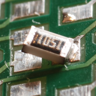
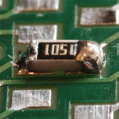
WRONG: The Part is pushed into the solder, but it doesn't have real contact
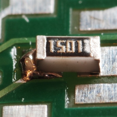
WRONG: A crocodile: the part stands upwards
If the part is on its final position, the other ins can be soldered. For resistors, capacitors and diodes, which have only two contacts, its the easiest to put the soldering-iron on the pad and add solder until a nice round connection is formed.
WRONG: Too little and too much solder
For parts with more than two contacts (microcontrollers, voltageregulators, the RS485 interface, ...) a leg on the opposite side of the part should be soldered. If the position of the part should again be corrected, this can be done in a small range with heating one solderconnection and moving the part around. But in this way, the other leg that is already soldered onto the PCB is twisted during movements, so this should be avoided. Now all other legs can be soldered.
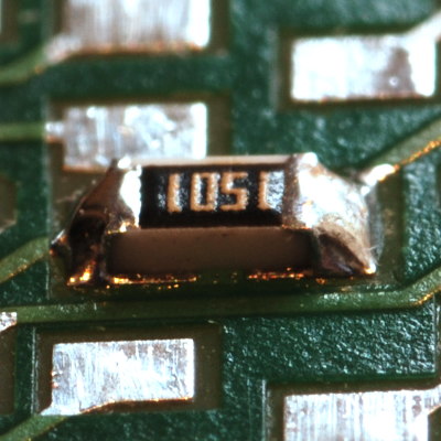
CORRECT: Thats what it should look like
If any shortcircuits between the legs are created, they can be removed with solderwick easily (but it could be necessary to resolder the legs).

